Step-by-Step On-Board Air Compressor with Viair 300p


This is a step-by-step guide on what I did to make my own On-Board Air Compressor mount on my Toyota Tacoma.
Step-by-step Process
Making the Base Mount Plate
Bought a screw and nut measuring gauge to find the size of the bolts in the engine bay. They are 8 mm
Bought 16 gauge steel sheet. I thought this would be best since it was thick enough to support the weight of the Viair without flexing. Other thinner gauges could possibly work in done in two or three layers. I thought it would be simpler to just have one, thicker layer.
Bought jigsaw blades to cut through metal and metal flap disc for angle grinder. The flap disc can in handle on multiple occasions.
Bought two 8 mm nylon lock nuts for two front studs in engine bay.
Bought an 8 mm nut coupler 1.25 pitch. Doesn’t have to be the same size since some lean will be okay. The nut couple will help span the height distance between the back bolt and the front two
Bought an 8 mm x 12 mm flange bolt to screw into the nut coupler from above the mount
Made a couple mock-ups of the mount using cardboard. This required iterating a few times slowly moving from a bigger piece to a smaller piece, trimming a little off each time to make it fit. Once I cut too much off and had to start over. Don’t get discouraged if this happened to you since this is why you are starting with cardboard - it is an easy and cheap mistake to fix. Once I get closer to my ideal size, I start to place the Viair on top to set the exact placement I want and how big the mount needs to be. Eventually I decided on my final mockup.
Now I traced that mockup onto the steel plate
Then I began cutting with the jigsaw and a 17 TPI blade. Since I was working with 16 gauge steel, I discovered that it was not easy for me to made tight turns. So I made oversized straight cuts, made a new starting location cut with the angle grinder cutting blade, and went back to a jigsaw until I got a large cutout of my mockup. I then trimmed the excess with progressively smaller corner cuts with the jigsaw and grided the excess with the flap disc.
Then I smoothed the edges with the flap disc
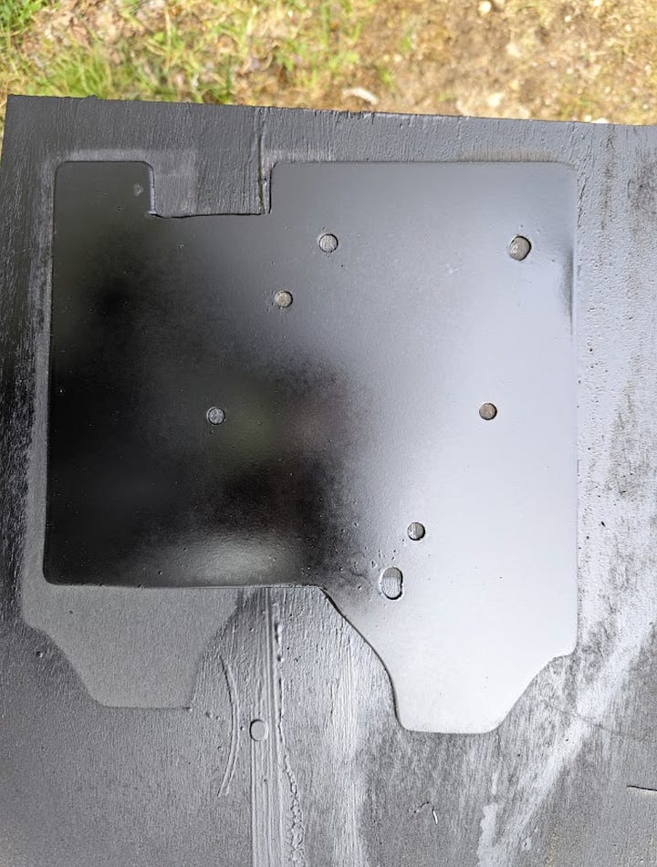
Next I needed to drill the holes for the mount to bolt to the existing bolts in the engine bay. Due to the awkward location, I thought it would be easier to press the bolt holes into the cardboard, cut out the holes, and mark on the steel plate rather than measuring distance and angles. This almost worked as my holes were almost aligned and only required slightly larger hole cuts to correct misalignment.
I used a step drill bit to cut a 5/16 hold for these 8mm bolts. The step drill bit is highly recommended if using 16 gauge steel since a regular bit will struggle and probably break ( I discovered this the hard way)
Deconstructing the Viair
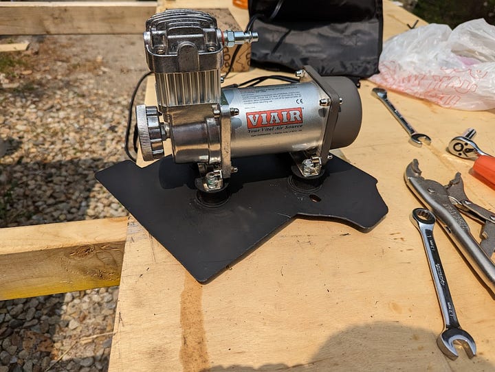
First you can unbolt the Viair compressor from its mounting legs using an allen hex wrench and a socket wrench to hold the nut
Once the leg braces are separated, you can pull out the rubber vibration isolators by pushing one side into the hole and pulling. This will be a bit tricky, but it just requires some force and finese.
Keep the legs as you’ll reuse them.
Then you can remove the top braces holding the handle on.
Use a wrench to unscrew the top coupler. This is just a female-to-female coupler attaching the air output from the air compressor to a tube running through the handle to the male I/M coupler used in stock form.
You should now just have the basic air compressor with the air output open. You will need to buy a male I/M coupler with ¼ flow size.
I then reattached the leg mounts with the allen wrench side facing the hole open side and the nut on the opposite side of the hole opening. This increases clearance for the nut of the new rubber isolators.
Marking your Viair Placement on the Mount
I then placed the mount in the engine bay and the flange bolt onto the mount (this helps with planning the Viair placement). Then I placed the disassembled Viair on top of the mount and moved it around to test a few positions that I liked. I decided on the opposite placement of Technique’s with the air filter facing towards the engine. While this does expose the filter to more debris kick up from the engine bay, I left enough room on the steel plate to protect the filter from debris kick up from below and then positioned it so the air filter box protects it from the front.
Once I found a position that I liked, I marked the holes with a sharpie. Make sure to leave enough clearance between the back bolt and closest leg hole for the vibration isolators
Also make sure to pick areas where there is nothing impeding the area directly below. This will most likely be the air filter bolt mount.
Then use a step drill bit to drill 5/16 holes for the leg mounts.
Painting/Weatherproofing your mount
If you got a galvanized or stainless steel sheet this step could be skipped, but if you went with steel, then you should paint the mount to reduce weathering and corrosion.
I used the flap disc to smooth down all drilled holes and edges
Clean both sides with isopropyl alcohol
Prime the surface with Rustoleum Self-Etching Primer
Apply your finishing coat. I used flat black Rustoleum spray paint.
Securing your Viair to the Mount
Buy 8 rubber washers with 8mm of 5/16 or closest hole size
The M8 vibration isolators will need to have the bolts trimmed down on both ends. The best way to do this for the Viair side is to line up the space you have between the vibration isolator and washer up against the leg mount to the allen hex head. Then mark that position with a sharpie. Then for the mount side, find the shortest clearance area of where you place your leg mount holes and mark that height.
Then cut the bolts using an angle grinder to length leaving a little extra length.
Then using the flap disc, grind down the top to a more exact fit test iteratively. Using the flap disc will also remove burs that would prevent the nylon bolt from going on.
Once these are cut to size, then place a rubber washer with the rubber vibration isolator bolts on top of the mount and secure with the nylon lock washer from below the mount. DO NOT tighten all the way since we will need the working space and movement next
Then grind down the top of the nylon lock nut a few millimeters to give clearance between the foot base and the allen hex bolt head.
The grinded nuts will need to be placed on the Viair leg base and have the rubber vibration isolator bolts screwed in from below with a rubber washer ontop. This can be down with finger strength at first and once the bolt reached the nylon, you will need to hold the nut with a 13 mm wrench and twist rubber vibration isolators with a vice grip. If measured the bolt cut correctly, the Viair feet will rest snuggly on top.
Then finish securing the nylon nuts from below.
Secure your air compressor to the bolts in the engine bay
Now place a rubber washer and fender washer on the front two bolts
Place a rubber washer and two fender bolts on the back bolt (the exact number of washers on the back bolt will vary based on the length of the coupling nut you got
Place the mount and Viair compressor on the bolts.
Insert the flange bolt through the back hole with a fender washer under the mount and secure the flange bolt to the coupling nut.
Secure the front two bolts with a 8 mm nylon locking nut
Congratulations on your new on board air compressor. You can now either use the stock air hose that came with the Viair compressor use a multi-tire inflate/deflate kit. I will also be posting soon how to make a hose extension to custom route your onboard air to any desired location.


